NUT FORMER
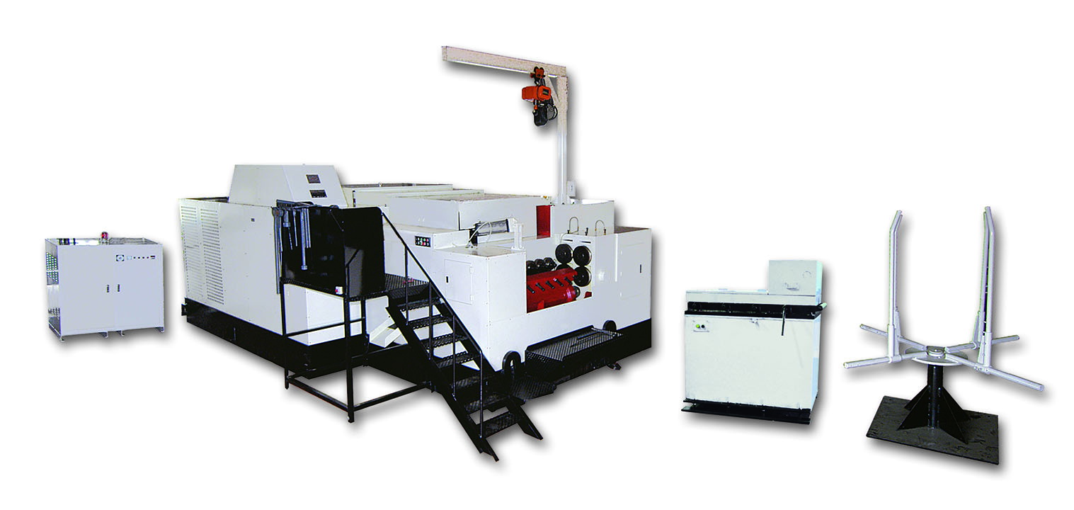
50B1


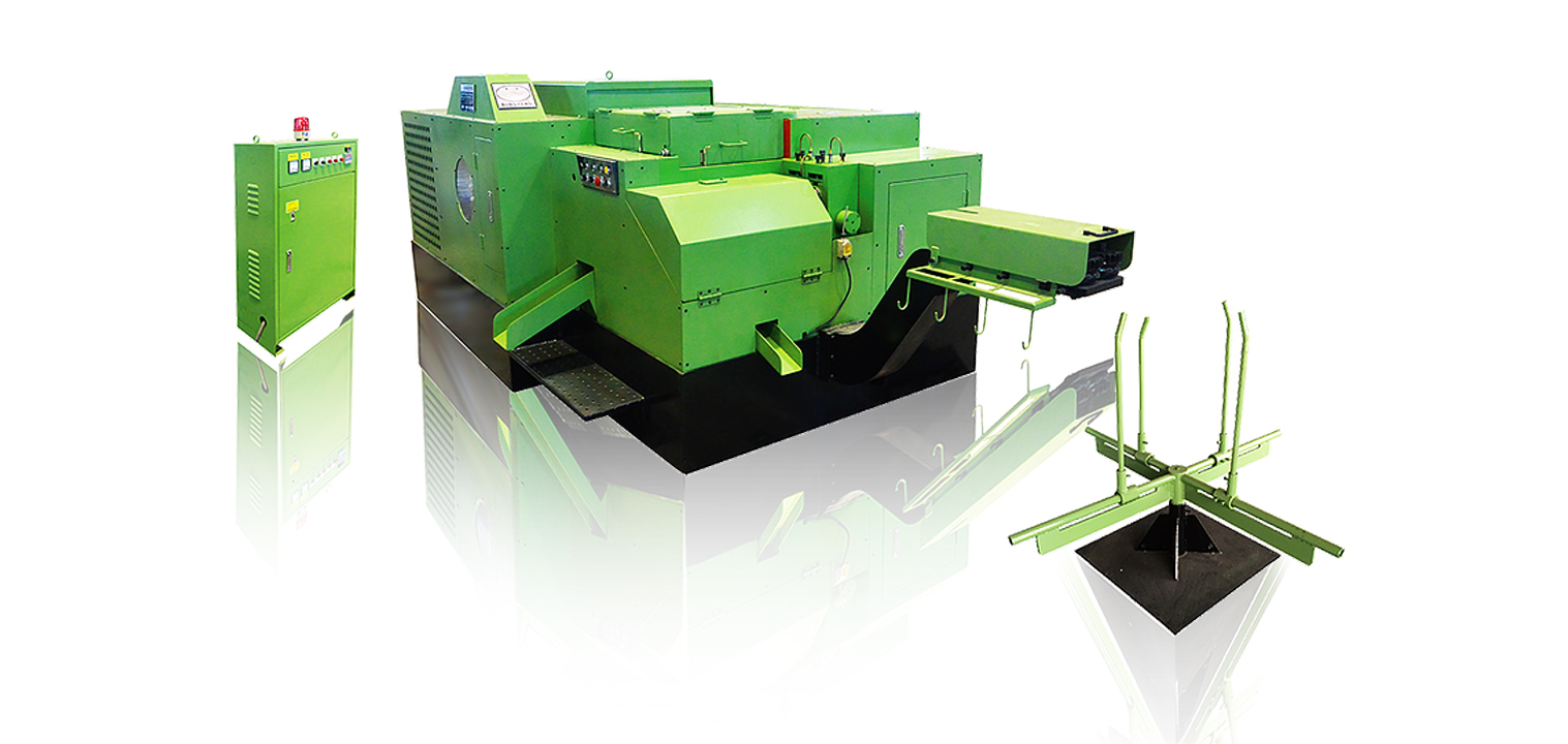
Nutformer
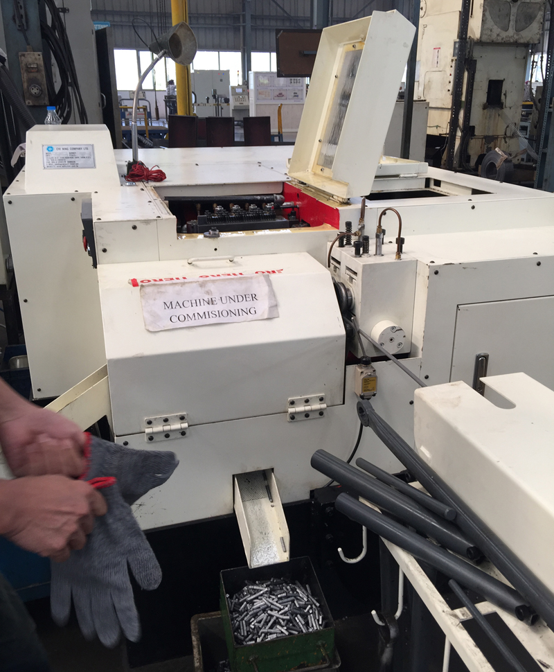
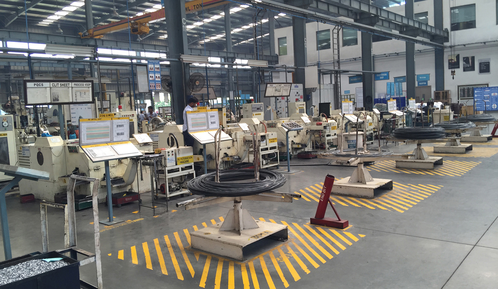
| NUT FORMER | |||||||||||||
|---|---|---|---|---|---|---|---|---|---|---|---|---|---|
|
SPECIFICATION |
MODEL |
CN-NF |
CN-NF |
CN-NF |
CN-NF |
CN-NF |
CN-NF |
CN-NF |
CN-NF |
CN-NF |
CN-NF |
CN-NF |
CN-NF |
|
FORGING STATION |
5S / 6S |
5S / 6S |
5S / 6S |
5S / 6S |
5S / 6S |
5S / 6S |
5S / 6S |
5S / 6S |
5S / 6S |
5S / 6S |
5S / 6S |
6S |
|
|
CUT-OFF DIA. |
(MM) |
11 |
14 |
16 |
19 |
22 |
24 |
26 |
30 |
33 |
36 |
41 |
45 |
|
CUT-OFF LENGTH |
(MM) |
(8) |
(15) |
(15) |
(20) |
(25) |
(25) |
(30) |
(35) |
(35) |
(45) |
(45) |
(50) |
|
KICK-OUT LENGTH |
(MM) |
(12) |
(20) |
(20) |
(25) |
(30) |
(35) |
(40) |
(45) |
(45) |
(50) |
(60) |
(60) |
|
CENTER DISTANCE |
(MM) |
50 |
60 |
70 |
80 |
80 |
100 |
100 |
120 |
140 |
150 |
165 |
190 |
|
RAM STROKE |
(MM) |
56 |
80 |
90 |
90 |
110 |
120 |
125 |
146 |
146 |
160 |
240 |
240 |
|
FORGING POWER |
(TON) |
60 |
90 |
110 |
150 |
200 |
250 |
300 |
360 |
450 |
530 |
630 |
800 |
|
PRODUCT SIZE |
(INCH) |
4# 1/4 |
1/4 3/8 |
1/4 7/16 |
5/16 1/2 |
5/16 9/16 |
3/8 5/8 |
3/8 5/8 |
1/2 3/4 |
1/2 7/8 |
5/8 1 |
3/4 1-1/8 |
7/8 1-1/4 |
|
OUTPUT PCS/MINUTE |
|
(350) |
(250) |
(220) |
(180) |
(160) |
(145) |
(130) |
(100) |
(85) |
(75) |
(75) |
(65) |
|
MAIN MOTOR |
(HP) |
(15) |
(20) |
(20) |
(30) |
(40) |
(50) |
(50) |
(75) |
(100) |
(175) |
(250) |
(350) |
|
PUMP MOTOR |
(HP) |
1 |
1 / 1 |
1 / 1 |
1 / 2 |
1 / 2 |
1 / 2 |
1 / 3 |
1 / 3 |
1 / 3 |
1 / 3 |
1 / 3 |
1 / 2 / 2 |
|
LUBRICANT |
(GALLON) |
200 |
300 |
300 |
350 |
350 |
380 |
420 |
620 |
620 |
750 |
900 |
1350 |
|
APPROX. WT |
(TON) |
4.5 / 5.0 |
7.5 / 8 |
8 / 10 |
12 / 14 |
15 / 17 |
20 / 23 |
24 / 28 |
40 / 41 |
41 / 45 |
55 / 63 |
65 / 71 |
108 |
|
FLOOR AREA |
(M) |
2.5 |
3.1 |
3.5 |
3.85 |
4.15 |
4.5 |
4.7 |
5.5 |
5.55 |
6.4 |
6.3 6.7 |
7.2 |
※The numbers in the brackets, relevant to speed and length, are just for reference. (Standard hex nuts are out of the rule.)
※The number of dies does not include cutting quill assembly core, and the floor area required excludes the area of wire stand.
| LONG STROKE FASTENER PART FORMER | |||||||||||||
|---|---|---|---|---|---|---|---|---|---|---|---|---|---|
|
SPECIFICATION |
MODEL |
CN-NF |
CN-NF |
CN-NF |
CN-NF |
CN-NF |
CN-NF |
CN-NF |
CN-NF |
CN-NF |
CN-NF |
CN-NF |
CN-NF |
|
FORGING STATION |
|
5SL/6SL |
5SL/6SL |
5SL/6SL |
5SL/6SL |
5SL/6SL |
5SL/6SL |
5SL/6SL |
5SL/6SL |
5SL/6SL |
5SL/6SL |
5SL/6SL |
6SL |
|
CUT-OFF DIA. |
(MM) |
11 |
14 |
16 |
19 |
22 |
24 |
26 |
30 |
33 |
36 |
41 |
45 |
|
CUT-OFF LENGTH |
(MM) |
(25) |
(40) |
(40) |
(60) |
(70) |
(80) |
(80) |
(80) |
(80) |
(80) |
(80) |
(80) |
|
KICK-OUT LENGTH |
(MM) |
(25) |
(40) |
(40) |
(60) |
(70) |
(80) |
(80) |
(80) |
(80) |
(80) |
(80) |
(80) |
|
CENTER DISTANCE |
(MM) |
50 |
60 |
70 |
80 |
80 |
100 |
100 |
120 |
140 |
150 |
165 |
190 |
|
FORGING POWER |
(TON) |
54 |
80 |
100 |
135 |
180 |
225 |
270 |
320 |
400 |
470 |
570 |
800 |
|
MAIN MOTOR |
(HP) |
(15) |
(20) |
(20) |
(30) |
(40) |
(50) |
(75) |
(125) |
(150) |
(200) |
(300) |
(350) |
|
PUMP MOTOR |
(HP) |
1 |
1/1 |
1/1 |
1/2 |
1/2 |
1/2 |
1/3 |
1/3 |
1/3 |
1/3 |
1/3 |
1/2/2 |
|
LUBRICANT |
(GALLON) |
200 |
300 |
300 |
350 |
350 |
380 |
420 |
620 |
620 |
750 |
900 |
1350 |
|
APPROX. WT |
(TON) |
4.5 / 5.0 |
7.5 / 8 |
8 / 10 |
12 / 14 |
15 / 17 |
20 / 23 |
24 / 28 |
40 / 42 |
41 / 45 |
55 / 63 |
65 / 71 |
108 |
|
FLOOR AREA REQUIRED |
(M) |
2.5 |
3.1 |
3.5 |
3.85 |
4.15 |
4.5 |
4.7 |
5.5 |
5.55 |
6.4 |
7.0 |
7.2 |
※The numbers in the brackets, relevant to speed and length, are just for reference. (Standard hex nuts are out of the rule.)
※The number of dies does not include cutting quill assembly core, and the floor area required excludes the area of wire stand.
| LONG STROKE FASTENER PART FORMER (P.K.O. system) | |||||||||||||
|---|---|---|---|---|---|---|---|---|---|---|---|---|---|
|
SPECIFICATION |
MODEL |
CN-C-PF |
CN-C-PF |
CN-C-PF |
CN-C-PF |
CN-C-PF |
CN-C-PF |
CN-C-PF |
CN-C-PF |
CN-C-PF |
CN-C-PF |
CN-C-PF |
|
|
FORGING STATION |
|
6SL/7SL |
6SL/7SL |
6SL/7SL |
6SL/7SL |
6SL/7SL |
5SL/6SL |
6SL |
6SL |
6SL |
6SL |
6SL |
|
|
CUT-OFF DIA. |
(MM) |
11 |
14 |
16 |
19 |
22 |
24 |
26 |
33 |
36 |
41 |
45 |
|
|
CUT-OFF LENGTH |
(MM) |
(40) |
(45) |
(50) |
(50) |
(60) |
(60) |
(75) |
(80) |
(80) |
(80) |
(90) |
|
|
PUNCH KICK-OUT LENGTH |
(MM) |
10 |
15 |
15 |
20 |
20 |
25 |
25 |
30 |
35 |
35 |
35 |
|
|
KICK-OUT LENGTH |
(MM) |
(40) |
(45) |
(50) |
(50) |
(60) |
(60) |
(80) |
(80) |
(80) |
(80) |
(90) |
|
|
CENTER DISTANCE |
(MM) |
55 |
60 |
70 |
80 |
90 |
100 |
112 |
140 |
150 |
165 |
190 |
|
|
FORGING POWER |
(TON) |
54 |
80 |
100 |
140 |
180 |
220 |
270 |
400 |
470 |
630 |
800 |
|
|
MAIN MOTOR |
(HP) |
(15) |
(20) |
(30) |
(40) |
(40) |
(50) |
(75) |
(150) |
(225) |
(300) |
(400) |
|
|
PUMP MOTOR |
(HP) |
1 |
1 / 1 |
1 / 1 |
1 / 2 |
1 / 2 |
1 / 2 |
1 / 3 |
1 / 3 |
1 / 3 |
1 / 2 / 2 |
1 / 2 / 2 |
|
|
LUBRICANT |
(GALLON) |
250 |
300 |
300 |
350 |
400 |
450 |
450 |
850 |
1150 |
1250 |
1400 |
|
|
APPROX. WT |
(TON) |
(6) |
(8.5) |
(11) |
(15) |
(19) |
(23) |
(31) |
(47) |
(65) |
(103) |
(130) |
|
|
FLOOR AREA REQUIRED |
(M) |
2.8 |
3.1 |
3.5 |
4.0 |
4.35 |
4.55 |
5.0 |
6.1 |
6.6 |
7.2 |
7.7 |
|
※The numbers in the brackets, relevant to speed and length, are just for reference. (Standard hex nuts are out of the rule.)
※The number of dies does not include cutting quill assembly core, and the floor area required excludes the area of wire stand.

